-40%
Sinclair ZX81 Upgrade Kit, 32k RAM Intern, Hires, Composite, Speicherton, vLA81.
€ 28.51
- Description
- Size Guide
Description
(English version below)ZX81 Upgrade Kit, um Ihren ZX81 (oder Timex Sinclair 1000) aufzupeppen. Für Issue 1 oder Issue 3 Hauptplatine sowie alle möglichen existierenden RAM-Konfigurationen habe ich schon gesorgt. Alles drin, was man braucht, und von einer Quelle aus Deutschland (also mir) und mit nur einmal Porto. Das Herzstück ist mit Abstand der vLA81 ULA Ersatz aus Neuseeland. Die andere Artikel sind auch alle neu und dieses Upgrade habe ich persönlich durchgeführt, mehrmals (sehe auch mein verkaufte Artikel) - und es ist Super!
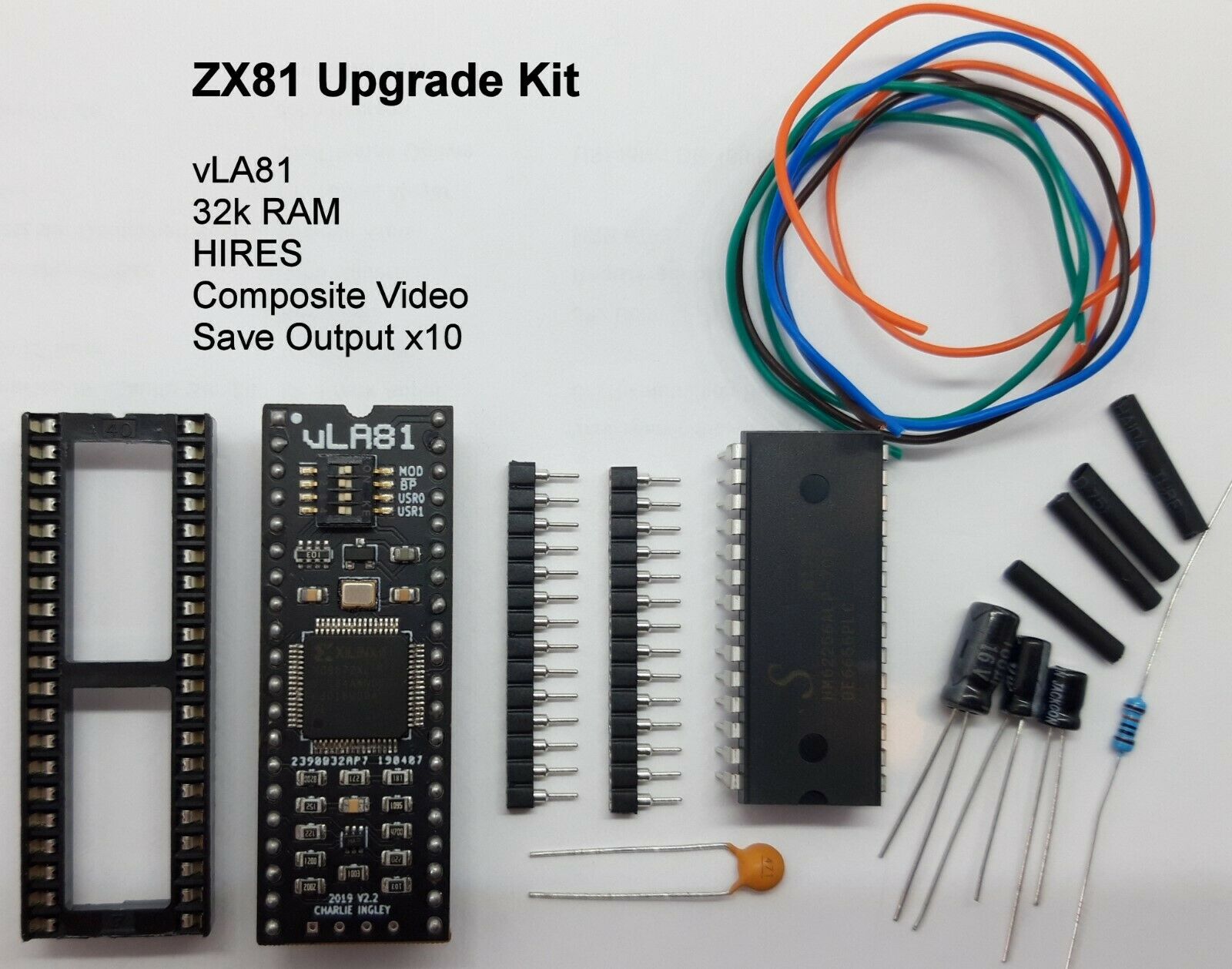
Das Kit beinhaltet:
Einen vLA81 Chip - Moderner ULA Ersatz (https://vdrivezx.files.wordpress.com/2019/12/vla81_user_manual_v1.3-1.pdf - Nur auf englisch).
Einen 32k SRAM 62256 Chip (28 pin).
40 pin Sockel für den vLA81 (falls nicht schon vorhanden).
2x 14 pin Präzisionsstreifen, um als Sockel zu dienen für den RAM IC (falls Sockel nicht schon vorhanden).
100 uF Kondensator, um den Composite Video Ausgang noch klarer zu machen.
4 Kabel (Farben können abweichen) für die 32k RAM Adressspuren.
4 Stück Schrumpfschlauch.
Einen Kondensator und einen Widerstand für die MIC Entdrosselung.
Ersatz Elkos für C3 und C5.
Dadurch bekommt Ihr ZX81:
Internes 16k oder 32k RAM (konfigurierbar auf upper, lower und mehr).
Einen direkten Composite Video Ausgang ohne weitere Modifikationen (nur den 100uF Kondensator).
Hires/WRX Kompatibilität.
Speicherton Ausgabe um 10x lauter.
Einen etwas kühlerer ZX81 durch den vLA81.
Beide neue Elkos für verbesserte Langlebigkeit.
Wie bau ich alles rein?
Um alles umzubauen, sollte man selbstbewusst und sauber mit einem Lötkolben umgehen können!
Wie viel Arbeit erforderlich ist, ist abhängig davon, wie Eure Hauptplatine ab Werk ausgestattet wurde. Bei Issue 1 Hauptplatinen sind Sockeln meistens schon vorhanden und das erleichtert alles (obwohl es vorkommen kann, dass der ULA Sockel nicht für die dickere vLA81 pins geeignet ist). Beim Issue 3 sind meistens überhaupt keine Sockeln vorhanden (und einen Issue 2 gibt es nicht)! Das Entlöten und Entfernen des 40 pin ULA IC und der insgesamt 28 RAM IC pins (1 grosser oder 2 kleinere chips) ist der schwerste Teil.
Beim neuen RAM IC sollten pins 1, 2, 23 und 26 nach außen gebogen werden (siehe Bild 3) und mit Adressspuren A11, A12, A13 und A14 verbunden werden - es gibt ein paar Möglichkeiten, wo diese Spuren an der Hauptplatine verfügbar sind, z.B. am Z80 IC, pins 1 bis 4 (siehe Bild 10).
Rechts (von oben) neben dem RAM IC ist ein jumper, beschriftet L1 und L2 bzw. LK1 und LK2. Falls vorhanden, sollte L1/LK1 getrennt oder entfernt werden. L2/LK2 müsste man verbinden, mit einem Stück Draht/Kabel.
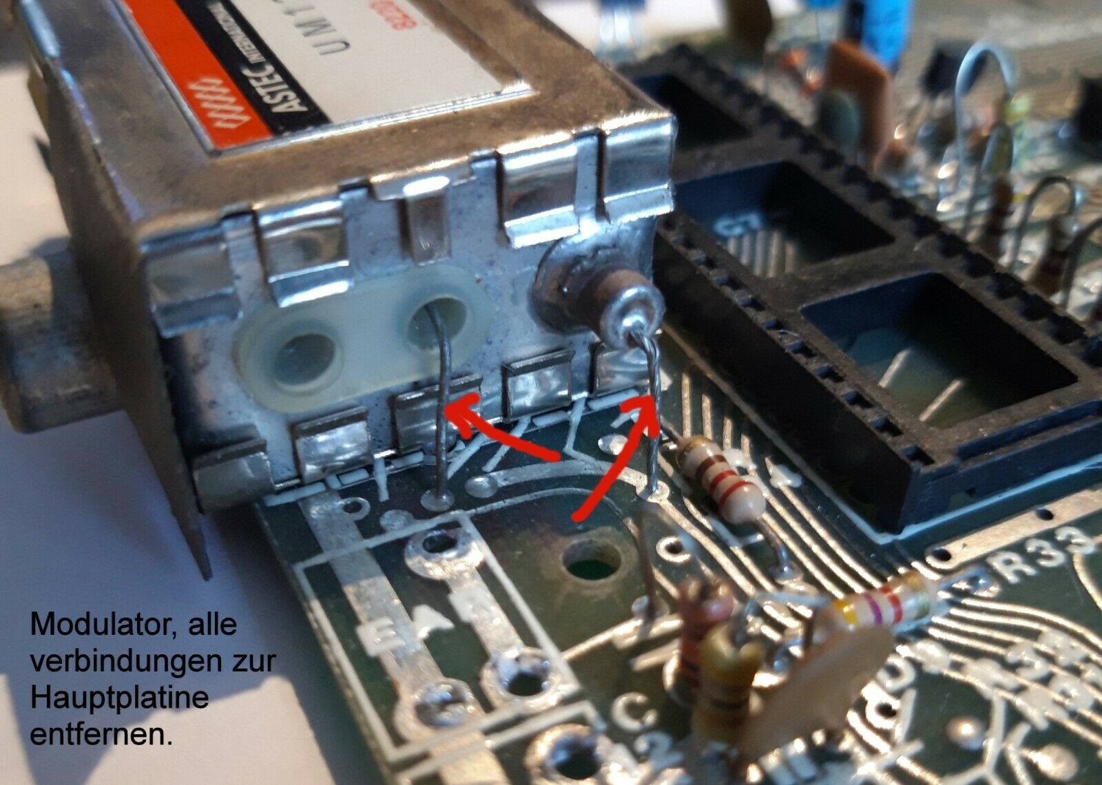
Euer Modulator Kästchen braucht keine von seinen 2 oder 3 Verbindungen zur Hauptplatine mehr (siehe Bild 7). Diese sollte man entlöten, rausziehen und nach oben biegen/befestigen oder komplett entfernen. Innerhalb des Modulators sollte man auch die Verbindung zum Videoausgang entfernen (bei UK und Europäischen ZX81 Modellen ist das das oberste Teil eines Widerstands). Den Positiv pin vom 100uF Kondensator sollte man an die Hauptplatine anschließen, wo das Videosignal von vLA81 (pin 16) zum Modulator ankommt (an der Hauptplatine, das 3. Loch vom Platinenrand) und den Negativ pin müsste man durch den Modulator führen und an den Videoausgang löten.
Die anderen 2 Kondensatoren sind 22uF Ersatz für C3 und 1uF Ersatz für C4.
Um den MIC Speichertonausgang zu entdrosseln, den Keramik-Kondensator und Widerstand hinten anlöten, wie im Bild 8 oder 9 gezeigt wird.
Bilder 3 und 4 sind Bespiele, wie es alles an einer Issue 1 Hauptplatine aussieht. Bestandteil dieser Sofortkauf-Auktion sind die Teile in Bild 1. Bild 10 zeigt ein Beispiel der ZX81 HiRes WRX Grafik. Bitte beachten Sie dass diese vLA81 Modul hat kein kleine Buchse unten wo man bei das andere Modell auch ein externe Schalter ranbringen kann, also der hier kann man nur oben an sein eigene Schalterblock umschalten (ausser man lötet selbst einen SMD Buchse am Unterseite).
Ich beantworte gerne Fragen vor und nach dem Kauf!
---------------------------------------------------------------------------
English Version:
ZX81 upgrade kit, to make your ZX81 (or Timex Sinclair 1000) more capable. It caters for issue 1 or issue 3 motherboards and all possible existing RAM configurations. Everything that you need is here, from one place (er, me) and with only one postage charge. The main component is the vLA81 ULA replacement chip from New Zealand. The other items are all new and I have personally carried out this upgrade, and it's great.
The kit includes:
A vLA81 chip - the modern ULA replacement (https://vdrivezx.files.wordpress.com/2019/12/vla81_user_manual_v1.3-1.pdf
).
A 32k SRAM 62256 chip (28 pin).
40 pin socket for the vLA81 (in case there isn't a socket already there).
2x 14 pin precision socket strips to socket the RAM IC (in case there isn't a socket already there).
100uF capacitor to connect the direct composite video to the video output, and it make the picture even better.
4 wires (colours may be different) for the 4 extra RAM address lines.
4 pieces of shrink tubing.
A capacitor and resistor with which to carry out the MIC signal boost.
Replacement capacitors for the existing C3 and C5.
With those items your ZX81 has:
Internal 16k or 32k RAM (configurable to upper, lower and more).
A direct composite video connection without the need to add anything (apart from the 100uF capacitor).
Hires/WRX compatible.
Slightly cooler running temperature due to the vLA81.
Both electrolytic capacitors changed for longer life.
How do I fit the items?
To be able to fit everything you should be able to use a soldering iron in a confident and accurate manner!
The amount of work involved depends on how your ZX81 motherboard is configured. Issue 1 motherboards tend to already have socketed chips, which is very helpful (although some sockets are too small for the thicker vLA81 pins). Issue 3 motherboards usually don't have any socketed chips (and issue 2's don't exist!). The de-soldering and removal of the 40 pin ULA IC and a total of 28 RAM IC pins (1 large or 2 small chips) is the hardest part.
Bend pins 1, 2, 23 and 26 of the new RAM chip upwards (see picture 3) and connect the 4 pins to the address lines A11, A12, A13 and A14. There are a few possible locations where these lines can be found, e.g. on the Z80 IC, pins 1 to 4 (see picture 10).
From above, to the right of the RAM chip is a jumper marked either L1 and L2 or LK1 and LK2. If present, L1/LK1 should be cut or completely removed. L2/LK2 has to be connected with some kind of wire. See pictures 8 and 9.
The modulator box will no longer need any of it's 2 (or 3 in some countries) connections to the motherboard (see picture 7). These should be de-soldered, pulled out and folded up out of the way or completely removed. Within the modulator there is a single connection to the video output (on European models, it is the top part of a resistor), this should also be removed and folded away to one side. The positive lead of the 100uF capacitor should be soldered into the position on the motherboard that connects to pin 16 of the vLA81 (the third small hole from the edge of the motherboard). The negative lead of the capacitor should be fed through the modulator and soldered to the video output, i.e. the centre of the RCA socket.
The other two capacitors are 22uF to replace C3 and 1uF to replace C4.
To boost the MIC sound output, solder the ceramic capacitor and the resistor to the positions shown in picture 8 or 9.
Pictures 3 and 4 are examples of how an Issue 1 motherboard looks with the RAM/vLA81 upgrade. Picture 1 shows all of the items in the kit and picture 10 shows an example of ZX81 WRX hires graphic. Please note that the vLA81 included does not have a small socket underneath the PCB for an external switch connection - this model vLA81 can only be switched using its own switch-block on the top (unless you solder an SMD socket to the underside).
I will gladly answer any questions you may have regarding fitting etc, both before and after the sale!
